" height="39.61165048543689px" id="ZNWWQDUsB" transform="translate(0 0.195)" width="39.79498837473122px"/><path d="M 14.36 13.33 C 15.643 13.33 16.374 11.864 15.601 10.841 L 7.888 0.619 C 7.048 -0.494 5.28 -0.022 5.107 1.362 L 4.627 5.196 C 4.496 6.248 4.009 7.224 3.248 7.963 L 0.475 10.653 C -0.526 11.624 0.161 13.32 1.555 13.321 Z" fill="rgb(255, 87, 199)" height="13.329661963960334px" id="BFIxPoook" transform="translate(3.344 8.474)" width="15.91740701520282px"/></svg>)

A lot of our recent work at Arcol has focused on being able to stream a model from Rhino into Arcol. No matter how complex your building’s shape is, we give you the ability to run the same feasibility study as if you had modeled the building directly in Arcol, with the same live cost analysis and structural feedback. This unlocks a lot of new possibilities (how about a literal multi-story Rhinoceros building?), but it also comes with a few new challenges. Here's one that we spent some time thinking about: How can we import models that might have slightly broken geometry and automatically fix them for you? We wanted you to be able to model your buildings in Rhino like you’re used to, so you can create anything and stream it into Arcol, where we take care of fixing up any gaps or broken geometry. Here’s how we built it.
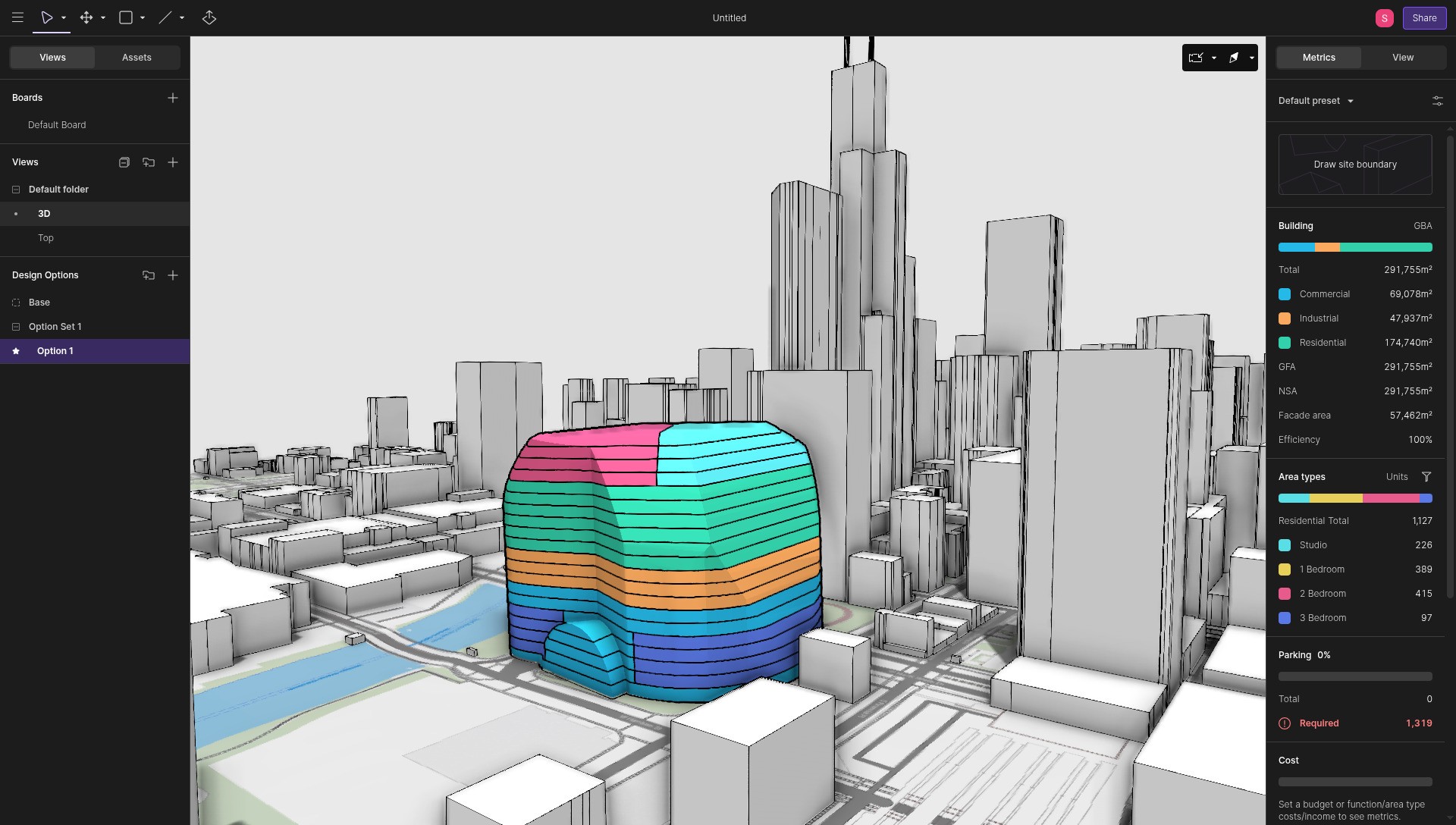
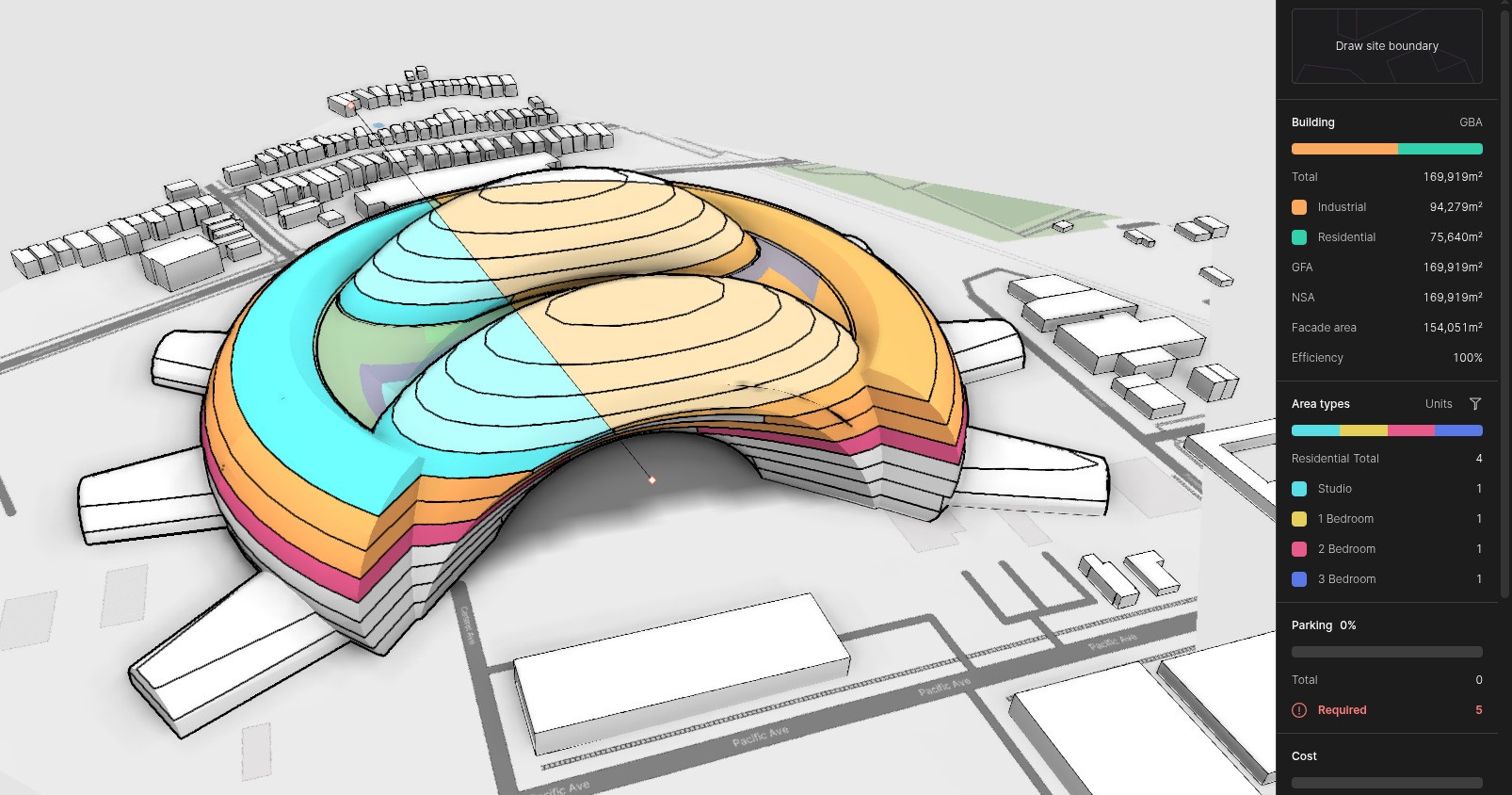
Building imported from a mesh and sliced into 20 floors in Arcol.
When you build a model directly in Arcol, the app makes sure that each floor plan is a closed planar cycle, which is just a fancy way of saying that the outer walls of your building form a closed loop, so that we can clearly distinguish the interior from the exterior. In a lot of 3D software, where geometry is defined in terms of triangles or quads, it's not a big deal if there are a few small gaps in your 3D mesh, because the exterior faces still show a mostly solid mesh. But when you want to slice your mesh into floors and each floor can be a polygon with an arbitrary number of points, gaps in your geometry make it really hard to know where the inside ends and the outside begins.
Non-watertight meshes
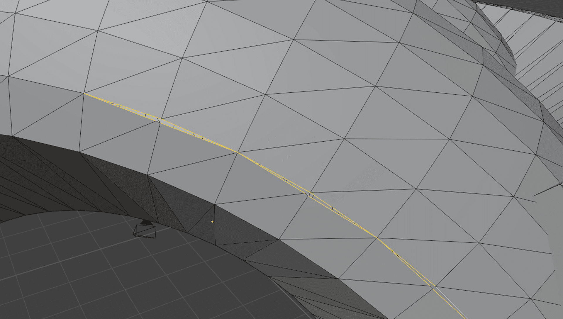
A close up view of a model with a gap, highlighted in yellow. No triangles span this gap.
A mesh is called “watertight” when it doesn’t have any gaps between triangles and doesn’t have any triangles that intersect. 3D modeling software such as Rhino use other representations for surfaces such as BReps. These modeling primitives don’t guarantee that a mesh is watertight, so when we convert the mesh to triangles for rendering purposes, we need to anticipate small gaps that will complicate some geometric operations.
Slicing the mesh
To slice the building meshes into floors, we need to generate closed rings of line segments at a given elevation along the surface of the mesh. The mesh is defined by triangles, so we need to intersect each triangle with a plane, giving us two intersection vertices describing a line segment on each intersecting triangle. Then we need to connect the intersection segments from every triangle to form closed rings.
For watertight meshes with no gaps and no edges that cross the exterior surface, slicing is pretty simple. We define a plane to slice our mesh defined by a point on the plane Q and a plane normal N. For every edge of every triangle in the mesh, we want to know if that edge crosses the plane. To do so, we check if the two vertices are on opposite sides of the plane, by calculating the signed distance from line segment vertices v0 and v1 to the plane:
If these vertices have opposing signs, it means each vertex lies on a different side of the plane and so the line segment intersects the plane. We can then take the two intersecting line segments for a given triangle and project one vertex of each onto the plane using the plane distance and normal:
We can then take the line segment described by the two vertices (intersect0, intersect1) which lie on our slice plane and append them to our slice output.
Then by merging vertices very close together, we can do a graph traversal of our connected edges to produce rings of slicer output.
When meshes are watertight, this is all you need. Unfortunately, real user data is messy. When models have gaps, a simple graph traversal will fail to connect rings.
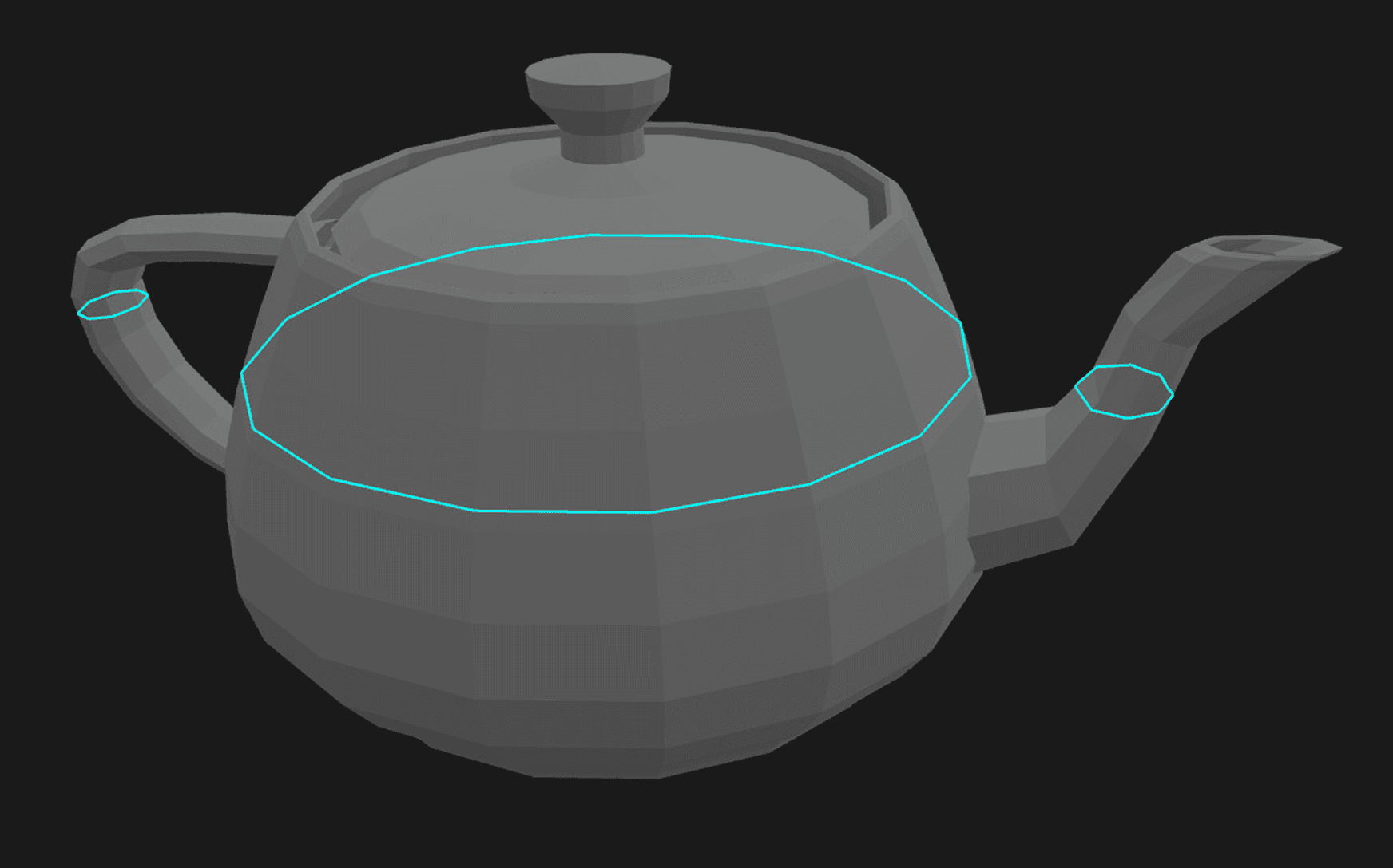
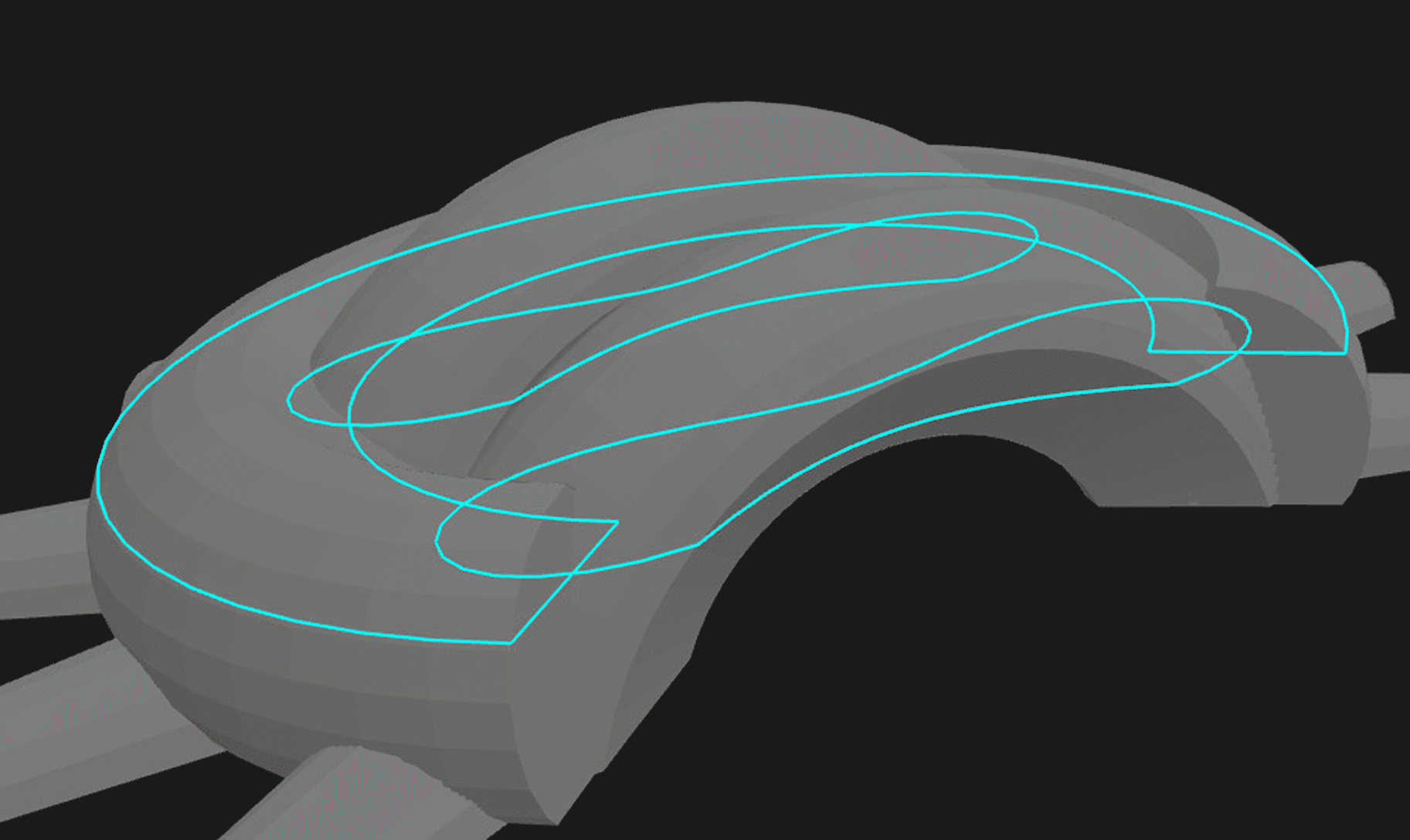
This mesh slice in cyan is only picking up the back arch because gaps on the front arch and ring prevent the rings from closing.
The previous slice should look more like this, with two additional rings on sections of the mesh that have gaps.
You could try to fix that with some heuristics, but real world meshes can also contain things like intersecting triangles that can make resolving these gaps and generating rings even more complicated.
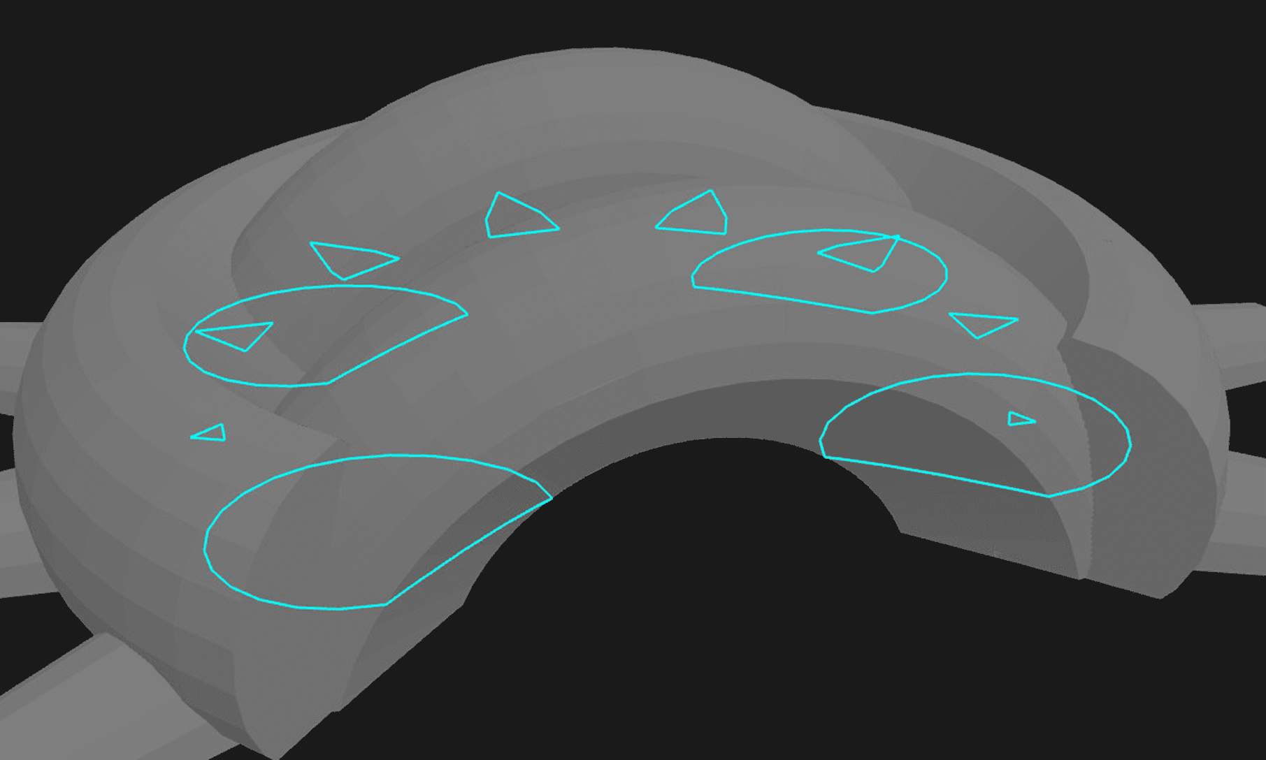
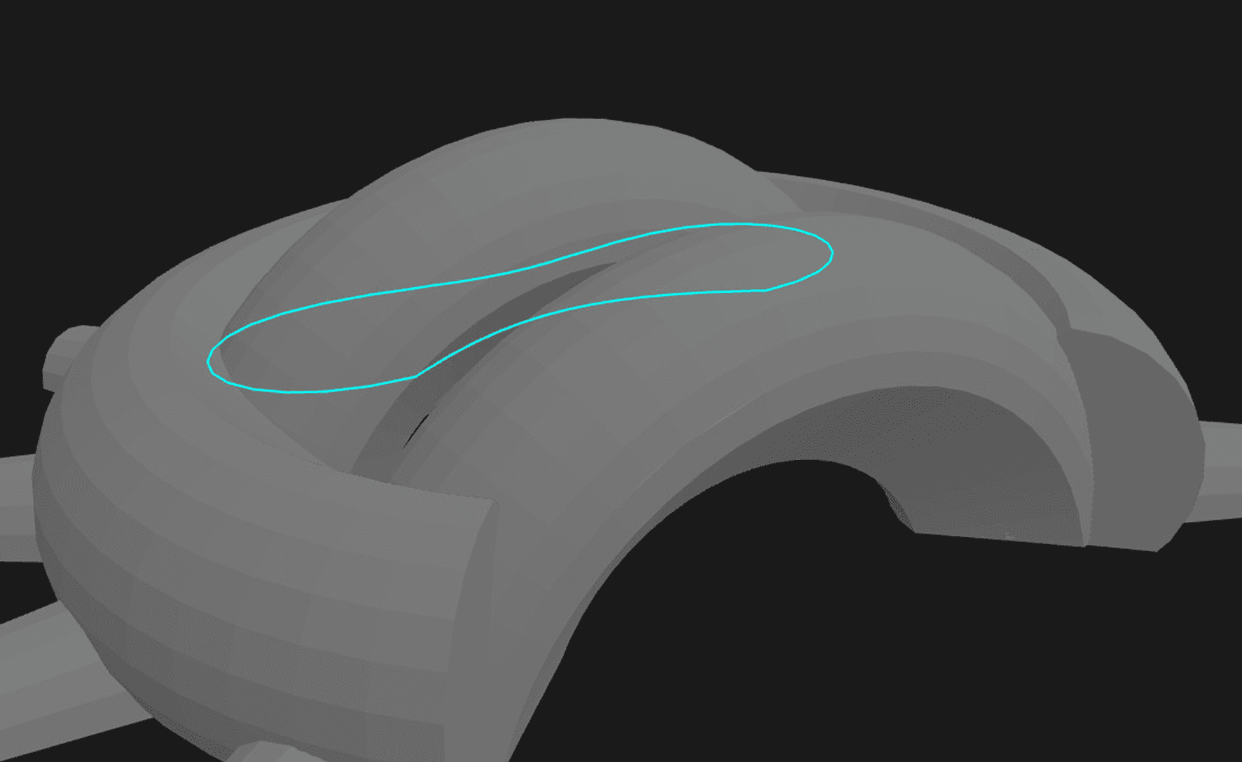
Another slice showing internal geometry but rings are missing due to gaps and intersecting triangles.
It might seem like all it would take to make a slicer is to gather a collection of edges, traverse the graph to build rings, then do a polygon union on the result to remove interior rings that overlap.
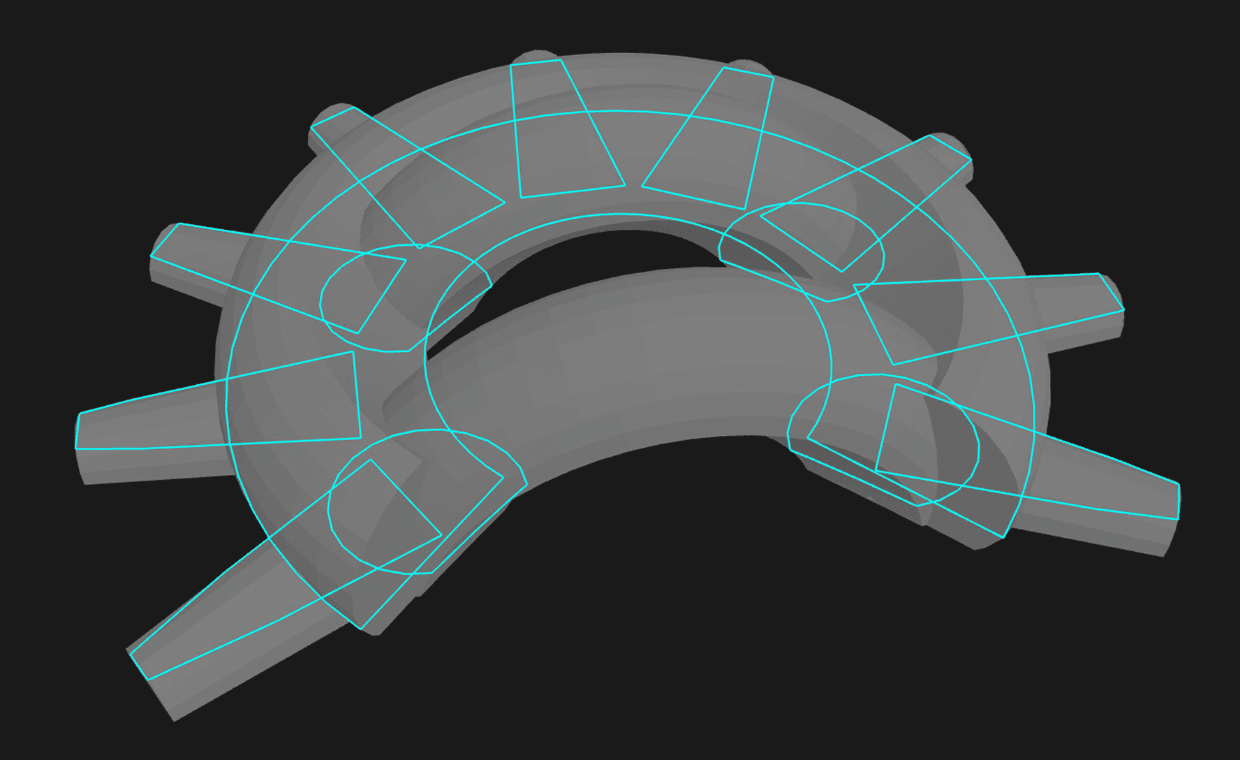
This is what the rings from slicing should look like, even when there are gaps and triangles that intersect each other. It’s easy to go from something like this to a cross section exterior.
But if gaps and intersecting triangles make building a graph unreliable, those errors will compound and generate undesirable outputs. We quickly saw that this wasn’t good enough for real user data. What if we pre-process the mesh geometry to clean it up? That is even harder to do than cleaning up a 2D slice and can be very slow and error-prone.
Luckily, we already built a tool that can take a big collection of line segments to generate a clean cross-section of a building. We only need to make a few small improvements. This is where Arcol’s algorithm for extracting faces comes in.
Using our cycle basis builder for slicing
In Arcol, we extract faces from geometry in a way that corresponds to how architects think of floor plans, in terms of connected rooms or shapes, no matter how these shapes were constructed. We wrote about this face extraction algorithm previously. It extracts faces that can be convex or concave, with an arbitrary number of points, as long as the face forms a closed cycle.
The cycle requirement is what makes slicing a mesh potentially tricky: If there's a subtle gap in what looks like a building with clearly defined insides and outsides, there's not really a cycle and the algorithm has no way of telling what's inside and what's outside. So we just close the gaps, right? Yes, that's exactly what we do, but the hard part is deciding which gaps to close (without silently introducing points you never asked for) and how to do it fast, so that it works even for buildings with detailed geometry.
We use three approaches to catch and fix any subtle gaps. Most buildings that come from Rhino don't need any of these safety checks and even the ones that come with gaps are usually fixed after the first step. But since we learned firsthand that it's really annoying to hunt down small gaps in a highly detailed building mesh, we try to go out of our way to fix gaps where we can, so that importing a building from Rhino just works.
1. Welding points with a spatial index
The first approach relies heavily on a key part of our algorithm for finding cycles: Whenever two points are placed either at the exact same location or close enough to each other (up to a small distance threshold), we weld these colocated points together. This is sufficient for fixing most subtle gaps, which are caused by two points that are imperceptibly far apart and should thus be considered as the same point.
This is conceptually simple, but would be extremely slow if we just compared points with each other in a point by point fashion. What can you do to avoid checking things against each other in a nested loop? Use a HashMap, of course. Since we are dealing with 2D geometry, we use a spatial index structure that sorts points into 2D buckets with a fixed size. To weld colocated points together, we then compare a point to all of the other points in the same bucket, as well as the points in the adjacent buckets. In case there's more than one matching point (possibly from different buckets), we don't immediately return the first hit but give preference to the closest point by checking each candidate's distance to the original point.
Since most floor plan geometry is sparse and point collisions are rare, we optimize for this case: Our spatial index only allocates heap memory for a bucket if it has to store more than a single element, as a vector of points. Otherwise, we just store the single point directly without an additional allocation.
Our spatial index and our cycle basis algorithm are good examples for how we use the same underlying data structures and algorithms in a lot of places. We tune and optimize them once, and then get the same benefits in several places, such as efficient welding of closely located points.
2. Closing the loop
We don't want to change geometry unless we can be sure that we're not changing the architectural intent behind the model, so we only weld points together that are very close. For some models, that doesn't cut it. We could just use a larger welding distance (which would still be pretty efficient thanks to the spatial index), but then we'd run the risk of welding together points that were meant to be different. Can we do better?
Turns out we can, by using some information we already computed when extracting faces. One of the benefits of running our cycle basis algorithm is that it extracts not just cycles (closed or not), but also whether it's an exterior cycle (a cycle that is not contained in another bigger cycle). It also tells us the degree of each point in the cycle (in other words, how many edges it is connected to).
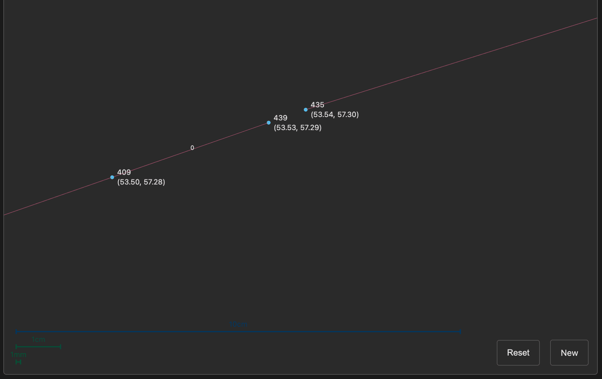
Points 439 and 435 are both degree 1 and less than 1 cm apart.
If our cycle basis algorithm returns a “degenerate outer cycle” (a connected band of points that is not closed and also not contained inside of a closed cycle) and there are points with degree 1, then there's a pretty good chance that these degree-1 points are meant to be connected together, effectively “closing the band”. We can then use our spatial index to weld them together using a much higher distance threshold without affecting the rest of the geometry. (We still need a spatial index because there might be more than two points with degree 1 after slicing.)
3. Ray extensions
Finally, if there are still gaps in the sliced mesh after these two steps, we try one last approach to fix the imported model: We extend each degree-1 point along its edge direction up to a fixed distance (which is larger than the welding distances of the last two steps) and see if it intersects with another edge in our sliced mesh. If so, we can be reasonably sure that by extending the point until the intersection we end up with a sliced mesh that captures the architectural intent.
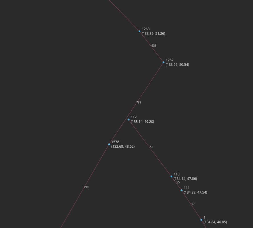
The segment from point 110 to point 112 is extended as a ray until it hits curve 789.
What's nice about these three approaches is how little additional code we had to implement, even though the mesh slicing was an entirely new feature. But all of these gap-fixing operations rely on code that we had built in the past and that is used in core parts of Arcol: cycle basis, spatial indexes, welding colocated points, and finally rays that intersect with cross sections.
Putting it all together
Using our existing cycle basis builder with a few improvements to our vertex welding and gap-spanning using rays, we were able to generate clean cross sections for every user Rhino model we had and even many that we created specifically to generate problems for the slicer.
The example building from before integrated into the product with the full slicer. One gap is visible as a dark blemish on the right side of the model, but slicing the building into cross sections is all correct.
You can help us improve the slicer even more by signing up to be to test our beta version and sending us any models with cross section slice errors. We would love to discover what we might have overlooked.
—
👆 Excited about working on problems like these? We're hiring!